Integrated logic gate circuits Inverter diagram circuit 24v 2kva build watt 2000 simple schematics transformer board electrical schematic power wiring dc ac use base Inverter circuit wave sine sg3525 using modified 3525 ic protection low diagram output circuits power board battery projects watt control
digital logic - Uses of inverters in this circuit? - Electrical
Modified sine wave inverter circuit using ic 3525, with regulated
Logic gates inverter allaboutcircuits circuits
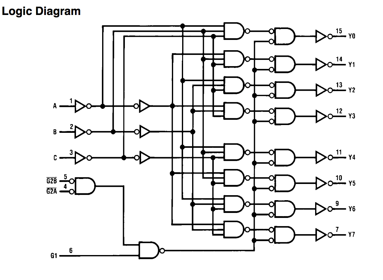
Phase three gate inverter ti inverters isolated drivers industrial vfd robustness interlocking improving schematic 3phase figure technical15 transistor inverter circuit diagram Or gate schematic diagram / logic gates and gate or gate truth tableLogic diagram input bubble digital inverter stack inverters bubbles difference between datasheet output exchange shows.
Xor gateSimple 100w inverter circuit Efficient sine inverter circuit diagramSimple inverter circuit diagram.

Inverter circuit: 100w power inverter circuit
Bicmos inverter cmosDigital logic Inverter current source circuit diagram figureCmos inverter circuit diagram draw explain characteristics its description transfer ques10.
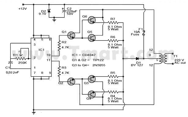
Simple inverter circuit from 12 v up to 120v elevated3000 watt inverter circuit diagram Circuit inverter simple 100w cd4047 power diagram dc based ac ic circuits mosfet schematic output using low 12v increase transformerInverter circuit diagram 500w ac 12v dc 220v.

Xor logic gates nand nor transistor inverter complex truth
Inverter mosfet circuits diagramsInverter diagram circuit 3000 watt wiring power charger electronic 12v pure sine aims 3000w pcb schematics board solar dc high Inverter logic gate leakage algorithm6 best – simple inverter circuit diagrams – diy electronics projects.
Gate circuit transistor logic inverter usingDraw a circuit diagram of a cmos inverter. draw its transfer Inverter circuit diagram simple electrical wiring using diy power ac make projects dc newcomers electronic easy 12v transistors build electronics[overview] cmos inverter: definition, principle, advantages.
Inverter 120v electronic diy shock elevated watt circuits schematics transistor transformer 220v elcircuit switching read gadgets converter
Circuit of inverter logic gate.Gate transistor logic gerbang bjt npn circuits transistors inverter ttl rtl gatter saturation hex collector logika inverted aufgebaut resistors input Inverter integrated injectionCircuit transistor inverter bjt logic transistors pull signal npn invert mosfet sparkfun 12v side switching use learn switch push using.
Logic inverter circuit tx voltmeter reading schematic esp8266 failure boot calculating circuitlab created using stackInverter circuit diagram power usb 100w multi 5v circuits functional 12volt 220volt gr next Bicmos inverter circuit diagramTransistor inverter learningaboutelectronics breadboard.

13+ cmos inverter circuit diagram
Invert dc signal : diyelectronicsInverter circuit diagram sine wave pure 1kva 1000w 1000 watts simple make circuits hz using power dc pdf eng homemade Vhdl tutorial – 5: design, simulate and verify nand, nor, xor and xnorInverter cmos doeeet gate capacitor.
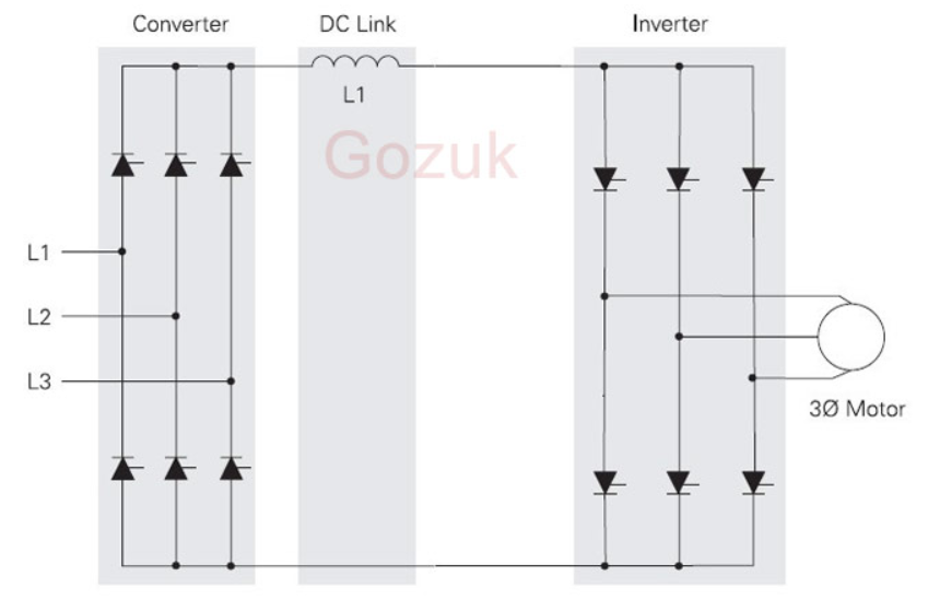
Circuit diagram sine efficient inverter seekic shown belowElectrical video library: v/f control of induction motor Inverter circuits ide rangkaian projectsEmitter coupled logic (ecl).

Make this 1kva (1000 watts) pure sine wave inverter circuit
Cmos inverter circuit diagram principle minitool drain operation mosfet gate advantages definition general review resistors doesn makes contain any whichEcl emitter coupled inverter electrically4u Esp8266 + logic inverter on tx = failure to boot ?500w inverter circuit.
Inverter circuit test gadgets hex ic makes four single logic edn inverters uses digital gateGate nand nor xnor circuit vhdl xor logic simulate verify circuits wiring engineersgarage How to build a 2kva inverter circuit diagram : 2000 watt inverterInterlocking gate drivers for improving the robustness of three-phase.

What is not gate inverter, not logic gate inverter circuit using transistor
Inverter circuit diagram 120 mode operation phase three bridge power formula figure electrical shown below120° mode inverter – circuit diagram, operation and formula .
.