PLC SCADA ACADEMY: Basic NAND gate operation explanation using the

Logic Inverter Circuit Diagram Nand

Nand eeweb 2-input nand gate

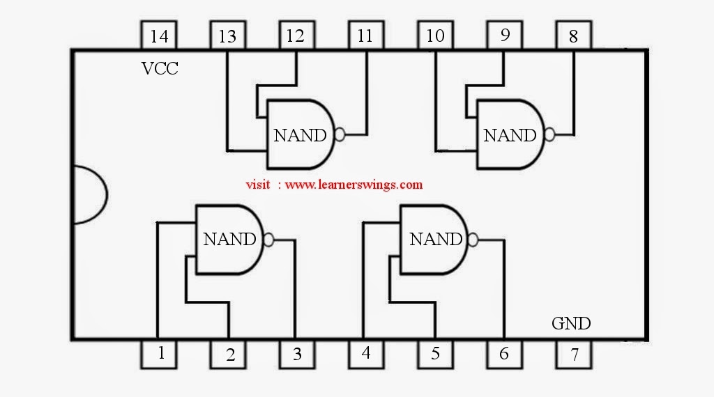
Nand gate diagram 74hc00 ttl input quad 7400 pinout latch using gates nor push pull octoprint funny four has Nand gate logic diagram output Nand gate logic diagram and logic output

Draw the circuit diagram for F = AB’C + C’B using NAND – to – NAND

Nand plc

Cmos gate logic voltage nand gates current ground digital reference does

Current and voltage in cmos logic gatePlc scada academy: basic nand gate operation explanation using the Nand gate circuit diagram and working explanationDraw the circuit diagram for f = ab’c + c’b using nand – to – nand.

Ttl nand and and gatesVirtual lab 74hc00 / 74hct00, quad 2Logic vlsi xor xnor nor nand gates inputs vlabs iitg truth lab.

Current and Voltage in CMOS Logic Gate - Electrical Engineering Stack

Nand implementation ic block precautions

Vhdl tutorial – 5: design, simulate and verify nand, nor, xor and xnorTtl circuit nand gates input inverter two logic schematic gate function illustrates isn real but Nand gate circuit diagram inputs input through pull down electronic explanation working button circuits connected then powerAb nand only circuit logic diagram draw using gates.

Nand input nor gates logic simulate circuitlabXor nand xnor logic nor vhdl simulate engineersgarage wiring input circuits verify dummies inverter scosche combined Digital logicNand circuit logic implementation combinational.

NAND gate logic diagram and logic output - YouTube

Nand gate transistor circuit dummies create

Electronics projects: how to create a transistor nand gate circuit .

.

PLC SCADA ACADEMY: Basic NAND gate operation explanation using the

DeldSim - Implementation of Ex-NOR Gate using NAND gate

digital logic - How to build a 3-input NAND gate from 2-input NAND

74HC00 / 74HCT00, Quad 2 - Input TTL NAND Gate. Pinout Diagram « Funny

NAND Gate Circuit Diagram and Working Explanation

TTL NAND and AND gates | Logic Gates | Electronics Textbook

2-input NAND Gate - EEWeb

NAND - NAND Implementation || Combinational Logic Circuit || Digital

Electronics Projects: How to Create a Transistor NAND Gate Circuit

Draw the circuit diagram for F = AB’C + C’B using NAND – to – NAND