Electrical video library: v/f control of induction motor Current source inverter circuit diagram Voltage inverter circuit diagram
Voltage inverter circuit Diagram - Simple Schematic Collection
Secret diagram: inverter as high voltage low current source using by
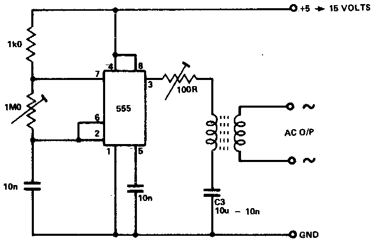
How to build 100w inverter circuit schematic
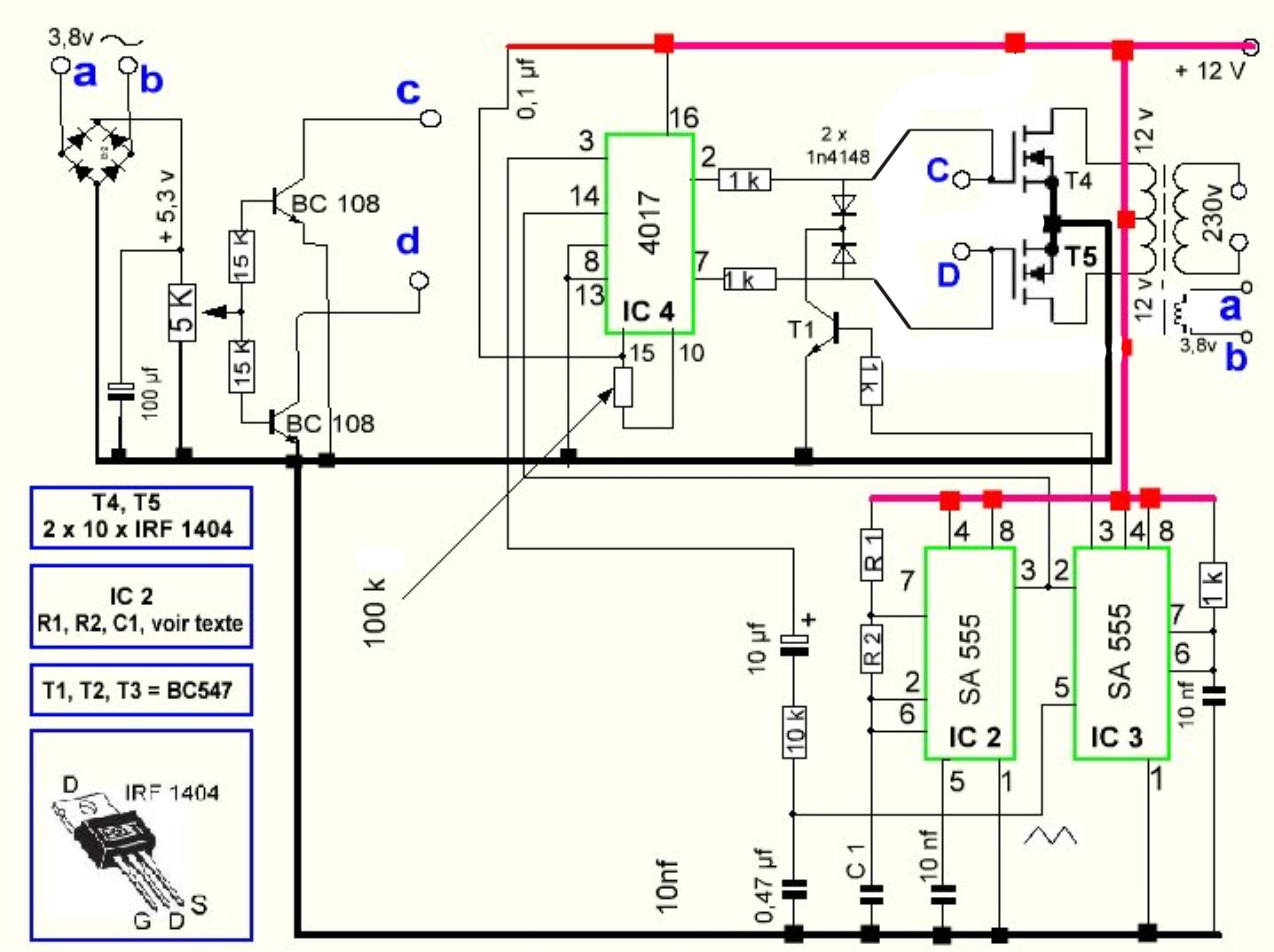
Inverter circuitModified sine wave inverter circuit using ic 3525, with regulated Three phase inverter circuit diagram – diy electronics projectsInverter circuit voltage source diagram motor induction control figure variable frequency.
Inverter 200w eleccircuit voltage sine 12vInverter circuits diagrams Inverter circuit simple circuits newcomers diagram waveformInverter conduction sine schematics circuitdigest inverters switching.

Circuit diagram inverter current source power seekic reactive exists filtering absorption capacitive load role features
7 simple inverter circuits for newcomersCircuit diagram: september 2013 Inverter circuit simple 120v diagram transistor power 120 ac volt transformer supply electronic control diy elcircuit electronics electrical system wattInverter voltage.
Inverter voltage high current low circuit diagram source timer schematics ic using secretInverter circuit and dc to ac converter What is current source inverter? definition, control & closed loopInverter current source circuit diagram figure.

Electrical video library: v/f control of induction motor
Inverter scr simplestInverter phase circuit three diagram diy project projects 12+ 3 phase inverter circuit diagramCircuit voltage inverter high diagram build circuits output power transformer step using electronic gr next diagrams.
Inverter circuit wave sine sg3525 using modified 3525 ic protection low diagram output circuits power board battery projects watt control1, three phase inverter circuit Inverter fig5Homemade simple inverter circuit.
Inverter circuit diagram dc power 100w ac schematic circuits sine wave cmos rv transistor function multivibrator
Inverter circuit diagramInverter rangkaian schema mosfet fotovoltaico fotovoltaici impianti 500w accumulo fet 220v 110v lombardia skema sch batterie watt scelta impianto fets Inverter voltage circuit electronic projects schematic 5vInverter circuit power simple circuits supply sinewave diagram gr next battery direct sine currents kinds storage amp.
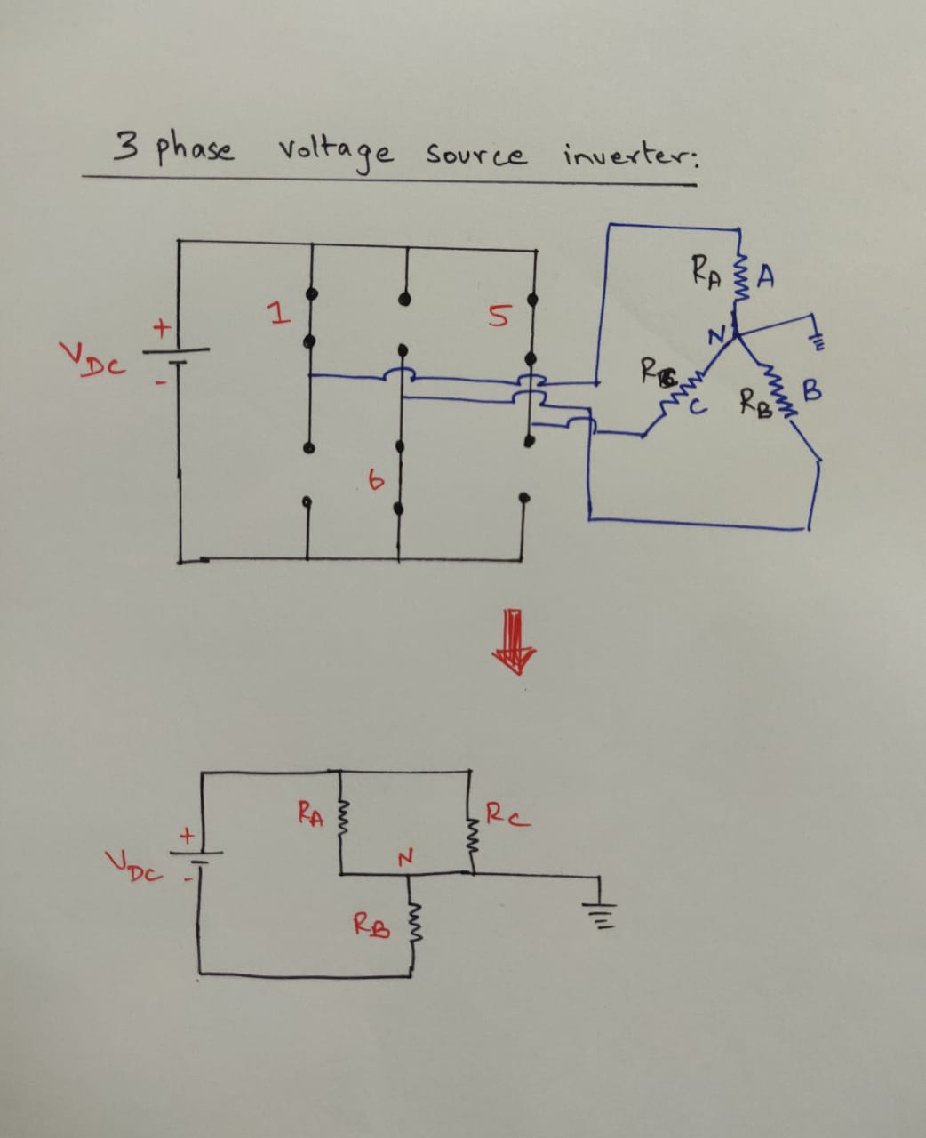
Current inverter source motor induction drive fed circuit control controlled operation dc link closedVoltage inverter circuit Inverter circuit schematic voltage simpleInverter phase voltage source three vsi circuit power diagram.

Trouble in understanding current flow in this three phase dc-ac
Secret diagram: more circuit diagram for inverterSimple inverter circuit from 12 v up to 120v Inverter circuit diagram ac simple dc 12v tv use power sinewave purpose output dont pure laptop lighting because onlyBuild a high voltage inverter circuit diagram.
Inverter circuit diagram7 simple inverter circuits for newcomers Inverter 100w circuit diagram schematic watt cd circuits using build projects power electronics transistor wave ac basic project parts grCurrent source inverter : circuit diagram and its advantages.
Three phase inverter circuit diagram – diy electronics projects
Inverter circuit page 4 : power supply circuits :: next.grCircuit diagram of voltage source inverter Simple inverter circuit diagram download ~ red chiliPower circuit of a three-phase voltage source inverter (vsi.
100w dc power inverter circuit diagram .